Jigs and Fixtures Explained: The 3-2-1 Principle and CNC Fixture Design
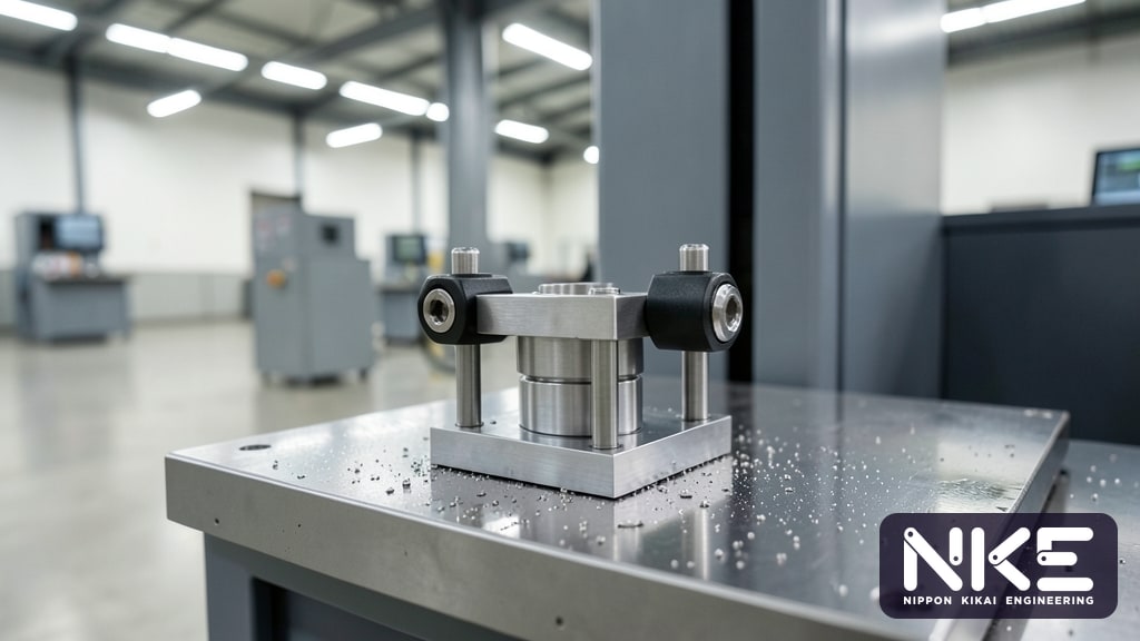
Whether you are turning, milling, drilling or assembling, a part can only be made accurately if it sits in exactly the same place every cycle and is held firmly while it is cut. That is the job of jigs and fixtures. Many plants invest in expensive CNC machines yet still fight drifting dimensions, intermittent scrap and slow changeovers, and a surprising share of those problems trace back to the fixture rather than the machine. This article covers the difference between jigs and fixtures, the 3-2-1 locating principle, good clamping practice and the extra requirements that come with automation.
Jigs vs Fixtures: What Is the Difference?
Both are production aids that locate and clamp a workpiece. The classic distinction is:
- Jig: holds the part and also guides the cutting tool, for example a drill jig with hardened drill bushings that put holes in the right place even on a simple drill press.
- Fixture: holds and locates the part only. Tool movement is controlled by the machine, as with a fixture bolted to a machining center table and used with a CNC program.
On Thai shop floors the word "jig" is often used for both. Since most metal cutting today happens on CNC machines, what people actually build are mostly fixtures. The same locating logic also applies to assembly jigs, welding jigs and checking fixtures.
The 3-2-1 Principle: The Foundation of Jig and Fixture Design
A free body has six degrees of freedom: translation along X, Y and Z, and rotation about each axis. A good fixture removes all six with the minimum number of contact points needed. That is the 3-2-1 rule.
- Three points on the primary datum stop translation normal to that plane and rotation about two axes. Spread them as far apart as the part allows for stability.
- Two points on the secondary datum stop one more translation and the remaining rotation.
- One point on the tertiary datum stops the last translation.
Locate on the drawing datums
Locators should sit on the datum features called out on the drawing, or on surfaces tied directly to critical tolerances, and the same datum scheme should be carried through every operation. Each datum change adds stacked error. Shafts are a clear example: the center holes at both ends usually serve as the datum throughout the process (see facing and centering, the first step in shaft machining).
Avoid over-constraint
Adding more locating points than needed makes parts rock, jam or distort. A common case is two round pins in two holes: a small variation in hole spacing and the part will not go on. The standard answer is one round pin plus one diamond (relieved) pin, which tolerates variation in hole pitch. On rough castings or forgings, locate on the three primary points first, then add adjustable or spring-loaded work supports for extra stiffness.
Clamping: Enough Force, Not Maximum Force
Once the part is located, clamping must keep it there throughout the cut. Key rules:
- Push the part into the locators, never away from them.
- Clamp directly over supports. Clamping over an unsupported area bends the part; when released it springs back and the machined face is no longer flat.
- Direct cutting forces into solid features. Plan the toolpath so the main cutting load goes into locators or the fixture body, not into the clamps.
- Respect thin walls. Thin or aluminum parts may need reduced clamp pressure for finishing passes, or wider contact pads to spread the load.
- Make the fixture itself rigid. A tall or slender fixture will vibrate and chatter no matter how stiff the machine is.
Manual, pneumatic and hydraulic clamping are all options. Pneumatic and hydraulic systems deliver consistent clamp force, whereas hand-tightened clamps vary from operator to operator.
Fixtures for Automation and Robot Machine Tending
When a robot replaces an operator, the fixture needs rethinking, because a robot cannot feel that a part is not seated properly.
- Lead-ins and chamfered pins let the part slide into position despite small robot positioning errors.
- Seating checks, such as air seating sensors or part-presence sensors, confirm the part is down before the cycle starts.
- Clamp confirmation through pressure switches or clamp position sensors tells the PLC and CNC that clamping has really finished.
- Chip management: let chips and coolant drain freely and add air blow-off on the locators every cycle. One small chip is enough to tilt a part.
- Poka-yoke features that allow the part to be loaded in only one orientation.
- Gripper clearance so the robot hand can enter and leave without hitting clamps.
For how to evaluate this kind of project, read Is robot CNC machine tending worth it? and see our CNC and robot machine tending solutions.
Faster changeovers
In high-mix plants, zero-point clamping systems or standardized base plates let you swap fixtures without re-indicating the setup each time, cutting changeover time, one of the major machine losses.
Common Jig and Fixture Design Mistakes
- Locating on convenient surfaces instead of the drawing datums.
- Over-constraining the part so it loads poorly or distorts.
- No escape route for chips, forcing frequent stops for cleaning.
- Unhardened locators that wear quickly and shift dimensions unnoticed.
- Wear parts that cannot be replaced without removing the whole fixture.
- No periodic fixture inspection, even though part accuracy depends on it directly.
Even with a perfect fixture, tool wear still moves dimensions over time. A highly repeatable fixture means measurement results reflect tool wear clearly, so offsets can be compensated meaningfully. Learn more about Auto Offset for FANUC CNC.
FAQ
Should we design fixtures in-house or bring in a specialist?
For simple parts loaded by hand, an in-house team can often do it. For tight tolerances, thin-walled parts, or fixtures that must work with robots and sensors, experienced automation engineers reduce the risk of multiple redesign loops.
How accurate does a fixture need to be?
As a rule of thumb, fixture error should be a small fraction of the part tolerance, leaving room for machine, tool and measurement variation. The right figure depends on each part's tolerances and is best agreed with your quality team.
Do we always need hydraulic clamping?
No. Low volumes or light cutting loads can work well with manual or pneumatic clamps. Hydraulics suit cases needing high clamp force in tight spaces, or automated cells that need consistent force and verifiable clamp status.
If you are planning a new process, improving existing jigs and fixtures, or integrating fixtures with robot loading, the NKE team can help from part analysis through design and build. Call 02-746-7196, add LINE @nke.th, or use our contact form.