Industrial Robot Safety: What a Safe Robot Cell Really Needs
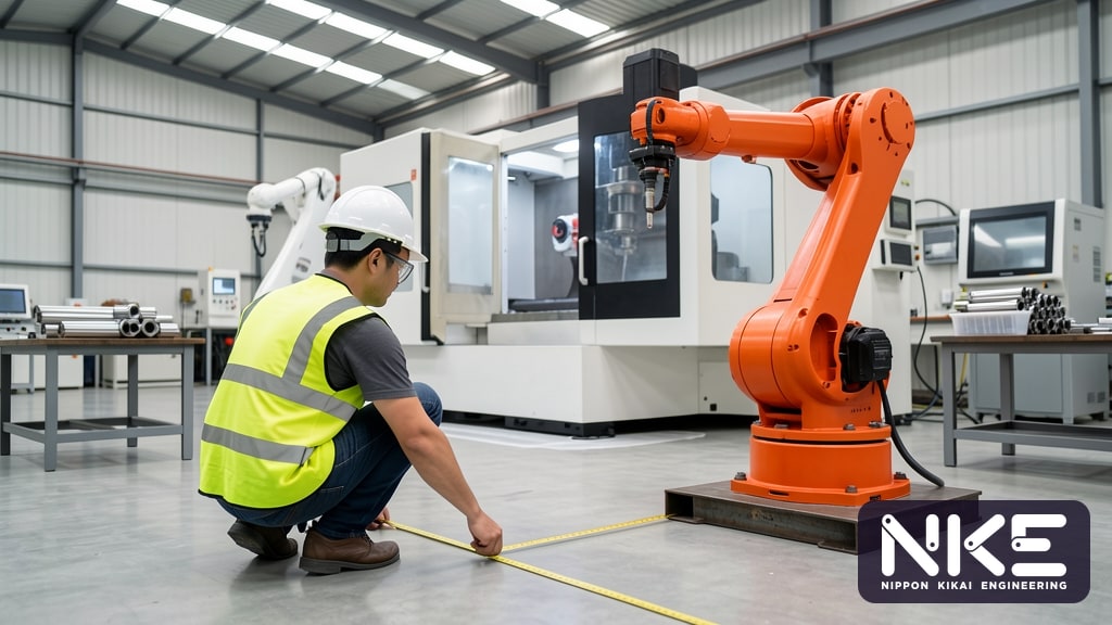
When a factory installs its first robot, the first question shouldn't only be about cycle time or payload. It should be: can people work around this machine safely? Industrial robot safety is not just a matter of putting up a fence. It is a system that has to be designed in from the start, covering layout, guarding devices, safety control logic, and the way operators and maintenance staff actually work. This article walks through the core elements of a safe robot cell, how safety distances are worked out, and the mistakes we see most often on the shop floor.
Industrial robot safety starts with a risk assessment
Industrial robots move fast, carry a lot of force and can change direction in ways a person standing nearby cannot predict. The main hazards in a robot cell usually come from:
- Being struck by the arm, or trapped between the robot and a column, structure or machine
- Parts or tools dropping from the gripper while the robot moves, for example after a loss of air or power
- Stored energy, such as air in cylinders, hydraulics, springs or gravity acting on vertical axes
- Teaching, troubleshooting and maintenance, which is when people get closest to the robot
The widely used international references are ISO 12100 for machinery risk assessment and risk reduction, the ISO 10218 series for robots and robot systems, and ISO 13849-1 for the reliability of safety-related control systems, expressed as a Performance Level (PL). The correct order for reducing risk is:
- Eliminate or reduce the hazard by design, for example a layout with no pinch points, or lower speeds where high speed isn't needed
- Add safeguarding, such as fences, interlocks and safety sensors
- Provide information and training, such as warning signs, manuals and work procedures
Signs and training are the last line of defence and should never replace physical protection. Alongside international standards, plants should also check the applicable Thai regulatory requirements with the relevant authorities or qualified safety professionals.
The main safeguarding devices in a robot cell
Fences and interlocked doors
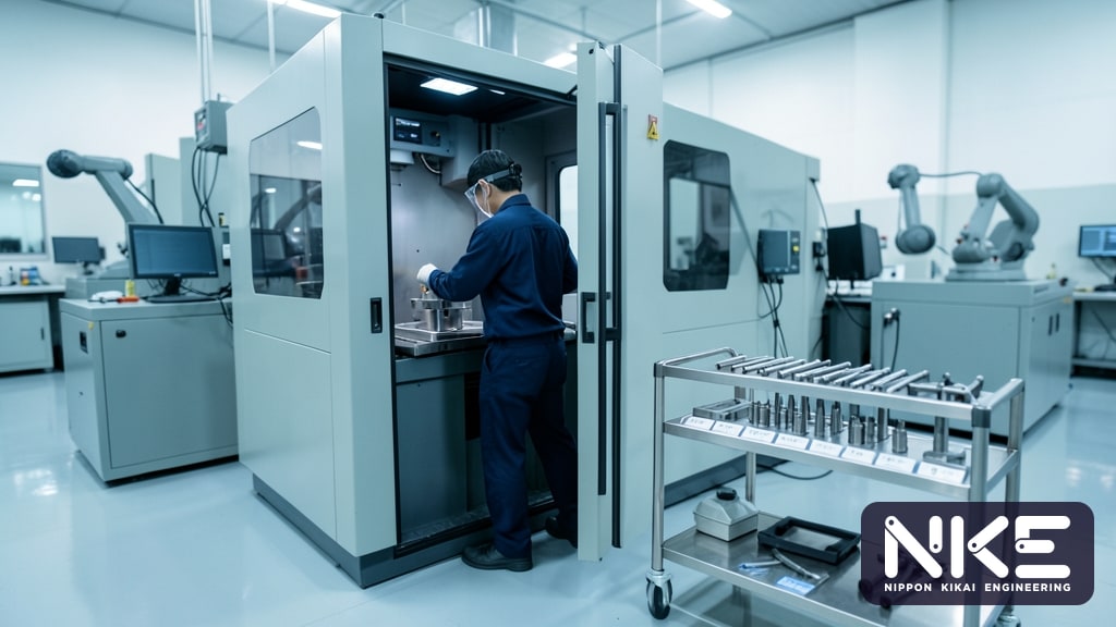
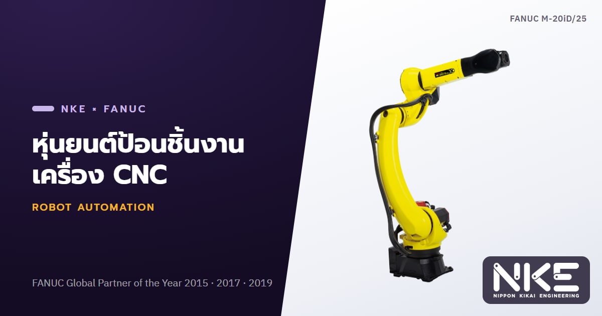
A fixed perimeter fence is still the most dependable form of protection. Fence height and mesh opening size must match the distance to the hazard so that hands and arms cannot reach in (guidance is given in ISO 13857). Access doors need interlock switches that bring the robot to a safe stop when opened, preferably a type that is hard to defeat, such as a coded switch. In machine tending cells, the interlocks between the robot and the CNC door matter just as much: the robot must not enter before the door is fully open, and the machine must not start cutting while the arm is still inside. For more on planning this kind of cell, see Is robot CNC machine tending worth it?
Light curtains and safety laser scanners
Where operators load or unload parts frequently, a door can slow things down. Light curtains across the opening or safety laser scanners watching a floor area are common alternatives. They allow quick access, but the mounting distance must be calculated correctly, and the design must stop people from walking around the sensor, crawling under it or standing undetected between the curtain and the robot.
Emergency stops and enabling switches
E-stop buttons must be easy to reach at the control cabinet, on the teach pendant and at every operator station. The enabling switch on the teach pendant is a three-position device: the robot can only move while it is held in the middle position. Letting go, or squeezing hard in a panic, stops the robot immediately.
Safety PLCs and safety relays
All of these devices must feed a safety-rated control circuit, not a standard PLC, because the circuit needs self-monitoring and redundancy to meet the required PL. A small cell may only need a safety relay, while cells with several zones or machines usually use a safety PLC for more flexible logic.
Safety distance: how far from the robot should a sensor be?
The principle behind ISO 13855 is simple: once a person crosses the sensor, the robot must come to a complete stop before that person can reach the hazard. The minimum mounting distance therefore depends on:
- The approach speed of the person, for which the standard gives reference values
- The overall stopping time, which is the sensor response, the safety circuit response and the robot braking time added together
- Sensor resolution; a light curtain that detects fingers can be mounted closer than one that only detects a body
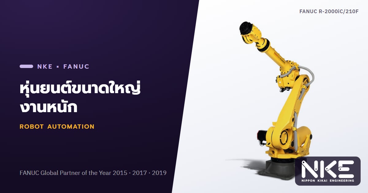
Hypothetical example: if the robot carries a heavy part at high speed, it takes longer to brake than with an empty gripper, so the sensor has to be further away. Always use worst-case stopping data (maximum payload and speed) and measure it on site after installation rather than relying on unloaded figures. This ties directly into robot sizing and reach, covered in How to choose a FANUC industrial robot.
Built-in robot safety functions and cobots
Modern robots include safety functions that make better cell design possible:
- Operating modes: T1 teach mode limits speed to a low value (ISO 10218 specifies no more than 250 mm/s at the tool centre point), while AUTO mode should only run with nobody inside the hazard zone
- Safety-rated position and speed limiting: functions such as FANUC DCS (Dual Check Safety) monitor position and speed through two channels, so the robot's working envelope can be restricted to less than its full reach. This can shrink the fence and the cell footprint, but the settings must be validated and changes tightly controlled
Collaborative robots rely on power and force limiting, with ISO/TS 15066 providing guidance on acceptable contact forces. A cobot is not automatically safe, though. Sharp grippers, parts with sharp edges, heavy loads or pinch points against tables and machines may still call for extra sensors or guarding, and the whole application always needs a risk assessment. For an overview of robot types, see Types of industrial robots.
Common mistakes on the shop floor
- Bypassing interlocks for convenience, such as leaving a spare actuator in the switch because the door has to be opened too often. The fix is to design loading points around real operating needs from day one
- Gaps under fences or beside conveyors that a person can slip through, especially where parts enter and leave the cell
- No protection against restart with someone inside; the reset button should be outside the cell with a clear view inside
- Skipping lockout/tagout during maintenance and forgetting to release air or other stored energy before entering
- Ignoring loss of air or power, letting the gripper open and drop the part; use valves or mechanisms that hold the grip
- Modifying the cell without re-validating safety, such as raising speed, changing the gripper or moving a sensor without re-measuring stopping time and reviewing the risk assessment
FAQ
Does every robot cell need a fence?
Not always. It depends on the risk assessment. Some applications can use safety laser scanners or cobots instead, but for fast or high-payload robots a fixed fence is often the simplest and most reliable solution.
Can a standard PLC handle safety signals?
It shouldn't. Safety signals such as E-stops and interlocks must go through a safety relay or safety PLC rated for the required PL. A standard PLC is fine for production logic and status display only.
How often should cell safety be reviewed?
Safety devices such as E-stops and interlocks should be function-tested regularly as part of the maintenance plan, and the risk assessment should be reviewed whenever the cell changes, whether that is the part, gripper, speed or layout.
A good robot cell should hit its production targets and let people work around it with confidence. If you are planning a new robot cell or want a second look at the safety of an existing one, NKE's team, a FANUC Global Partner, can help from layout and device selection through to installation and testing. See our factory automation services or contact NKE on 02-746-7196 or LINE @nke.th.